Seg3D Pages
Web pages for Seg3D
LayerManagerWindow
Category
Seg3DWindows
Description
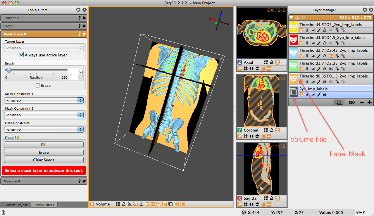
The layer manager window is the last of the three windows that open by default upon launching Seg3D. This window is positioned to the right side of the Seg3D window pane and contains all of the mask and volume files involved with the session. If a file is not selected when Seg3D launches, this window will be blank, otherwise it will contain the volume and mask surface files associated with the opened file.
The layer manager window is the last of the three windows that open by default upon launching Seg3D. This window is positioned to the right side of the Seg3D window pane and contains all of the mask and volume files involved with the session. If a file is not selected when Seg3D launches, this window will be blank, otherwise it will contain the volume and mask surface files associated with the opened file.
A volume file is represented by a gray image with multiple stacked planes. A label mask is represented by a colored icon with a white mask in the middle. The colors correspond to the label masks seen in the viewer windows. Names of label masks are, by default, a conglomeration of the tools applied to the original volume. For example, in the image Figure 4.3 five label masks have been created from the volume file ’2yo_Imp_labels.’ The uppermost mask (in yellow) has the name ’Threshold4.5TO5_2yo_Imp_labels.’ This name was generated because the threshold tool, with values between 4.5 and 5, was applied to the original volume file. If another tool were to be applied on the yellow mask, the new mask would state the name of the tool, followed by the complete name of the yellow label mask. Names of masks can be manually changed by clicking the current name and typing in the desired text.


Table 4.1: List of icons and actions available for each layer.
Each volume or mask label has standard, associated icons below their names. Table 4.1 displays and describes each of these icons. These icons represent tools that are available for each individual layer.

Table 4.2: List of icons and actions available at the top of each layer group.
Layers in Seg3D are arranged into layer groups. Layer groups are formed with layers that have the same geometric information, that is the same origin, spacing, and size. Groups are separated by panels with an orange header. Generally speaking, most tools and filters requiring more than one input can only operate on layers in the same group (and therefore the same grid geometry).


Table 4.3: List of icons and actions available at the bottom of each layer group.
There are some functions that are operated as a group. These are indicated by the icons on the top of the pane, in the orange bar (Shown in Table 4.2). Additionally, there are some other icons at the bottom of the group that control some of the group functions (Table 4.3). Hovering the cursor over the icon will display the the use of each additional icon.